2.1. Siemens PLC first steps
Note
All project are written in TIA portal v15. The exercise can be in any version, also in step 7.
2.1.1. S7-1200 Overview
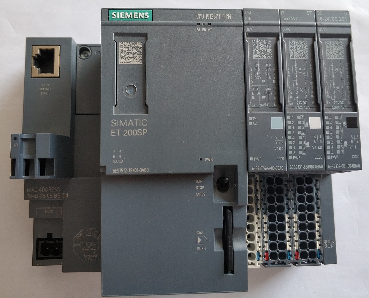
We will use S7-1200 PLC. The model that we will be using is 1215C direct current (DC). The advantage of S7-1200 is the price and the integrated IO.
As shown in the image this PLC have 14 digital inputs (DI) and 10 digital outputs (DQ) and 2 analog inputs (AI) and 2 analog outputs (AQ). It have also High speed counters (HSC) and Pulse generators (PWM).
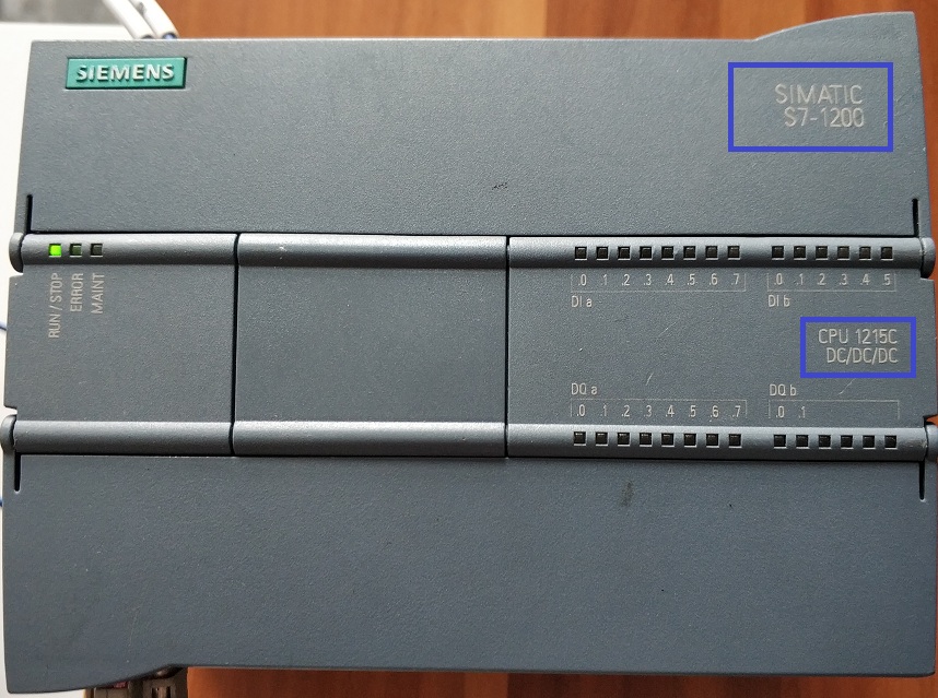
Siemens S7-1200 PLC
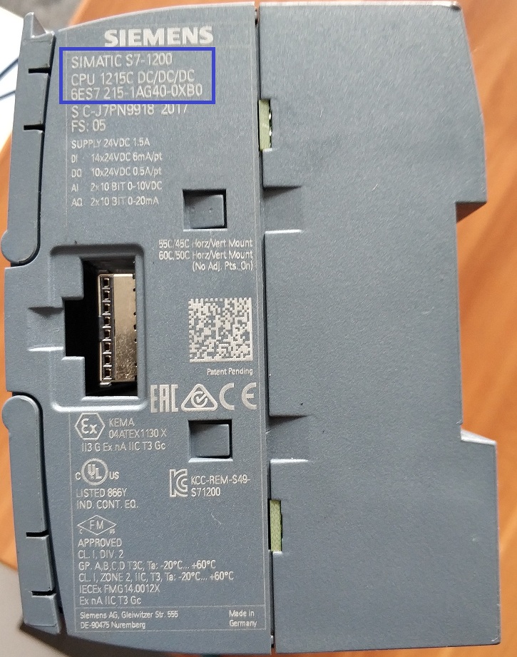
CPU 1215C DC/DC/DC 6ES7 215-1AG40-0XB0
2.1.2. New Tia Portal project
In this section we will create a new Tia Portal project and create a new device. The new device will be the PLC we see in the previous section.
New TIA portal project
2.1.2.1. Set Ip Address
After creating a new PLC, the first step is to set its IP address. To set the Ip address, you need to open the property dialog of the PLC. If you click on the PLC image you need to go to PROFINET interface [X1], Ethernet addresses. If you click on the Ethernet ports on the PLC image you can see directly the entry Ethernet addresses.
Set IP address
2.1.2.2. System and Clock memory
A clock in any CPU is necessary to provide timing. Select the PLC and in the property dialog check the 2 check boxes: System memory bits and Clock memory bits.
System and Clock memory
Once these flags are checked, the PLC provide different system variables. For example AlwaysTrue is a variable that is always true i.e. have always value 1. The variable Clock_1Hz is a variable that have the form of a square wave, where it is for 0.5s is high and for 0.5s low.
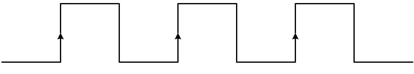
CPU Clock
2.1.2.3. Tia portal navigation
Tia portal main windows is a dockable user interface. The following animation show how to navigate the main window.
TIA portal windows navigation
2.1.2.4. Download configuration
Download configuration
2.1.2.5. Online and diagnostics
Online and diagnostics
2.1.3. Simple Program
Lets suppose we wire a lamp to the first digital output of the PLC, labeled DQa .0 on the PLC chassis. In the configuration of the PLC we give that output a name or a tag. The name can also be given in the PLC tags table. The following animation illustrate how to create a tag and write a small program in order to blink the lamp.
Blink an output with a frequency of 1Hz
In this example we use the tag or variable Clock_1Hz in order to turn on and off the lamp, output, with a frequency of 1Hz. Remember, the clock have a wave square shape. If we want to blink the output with different timing, for example with a period of 2 seconds, the frequency that should be used is 1/2=0.5Hz. So clock_0.5Hz can be used.