2.12. Simple project
Download Exercises solutions
The layout of this project is shown in the following image:
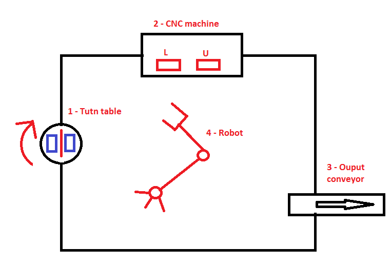
Turn table (1) with 2 positions, CNC machine (2) with 2 position for loading and unloading, exit conveyor (3) and industrial robot (4)
The process flow should be clear, the robot take a raw part from the turn table and put it in the CNC machine, in the loading position L. Then take the machined part from the unloading position U, and put it on the exit conveyor. The cycle continue in this way. The external position of the table is loaded by a person.
In the previous exercise we already write the function blocks for the conveyor and turn table, feel free to modify the logic if necessary, if you didn’t consider some situation before. The goal of this project is to show how to organize the software.
the layout represent a cell. In this cell we can identify three stations: Turntable, machine and conveyor.
Stations normally are independent from each others. For example the conveyor don’t care neither need to know anything about the turntable neither the machine, and vice versa.
The robot is the only connection between all stations.
From this point of view we can write the logic of every station independently from other stations. This is the approach taken also when writing the logic of very big production lines: break it down and you will see that a very complicated production line will be easy to implement. Every station have it sown defined job.
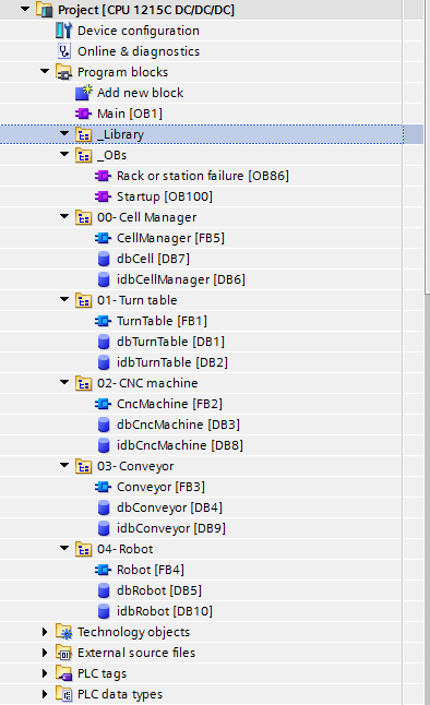
At this point we have one cell, three station and one robot. If the PLC control more than one cell, every cell should have its own folder. In this project, we have only one cell and one PLC. It is optional to create a cell folder. Keep in mind always future integration, so never limit your software to the current situation.
Three folders are created for every station and one folder for the robot. another folder can be created for general management of the cell.
Every station has it own main function and main global data block and instance data block.
A folder called _Library is created, where general functions will be placed. In the previous chapter we see how to create an S7 library. We will add that library to the project and use conveyor and turntable FBs from it.
OB1 must contain only function calls. In the following image we can see the call to other functions. It is better to use SCL to call other functions because it is more compact. Notice the name of the function calls in SCL and in Ladder.
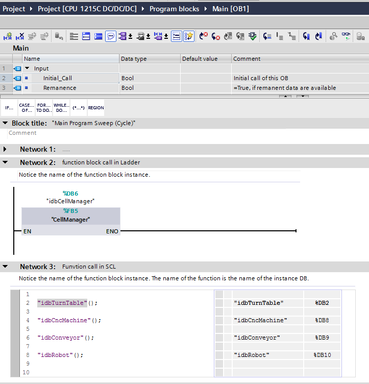
The main function blocks of the station, should not have input neither outputs. The call should appear on one line.
In the following sections we will examine every station. The developlent will be done without caring too much about where the physical IO are connected.
As we think always in local variables at the beginning, we don’t care where I and Q are assigned. Connecting those IO will be done when the logic is completed.
Of course we need to know which IO we have in order to avoid to invent our own project. Electrical drawing should be always consulted.